generate 3d from a 2d drawing
| | This article's factual accuracy may exist compromised due to out-of-date information. (Oct 2019) |
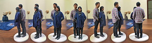
A 3D selfie in ane:twenty scale printed past Shapeways using gypsum-based printing, created by Madurodam miniature park from second pictures taken at its Fantasitron photo berth.

3D models are generated from 2D pictures taken at the Fantasitron 3D photograph booth at Madurodam

Generating and reconstructing 3D shapes from single or multi-view depth maps or silhouettes [ane]
3D reconstruction from multiple images is the cosmos of three-dimensional models from a set up of images. It is the reverse process of obtaining 2d images from 3D scenes.
The essence of an image is a projection from a 3D scene onto a 2D plane, during which procedure the depth is lost. The 3D indicate respective to a specific image signal is constrained to be on the line of sight. From a single image, it is impossible to determine which point on this line corresponds to the paradigm point. If ii images are available, then the position of a 3D point can exist found as the intersection of the two projection rays. This process is referred to as triangulation. The key for this process is the relations between multiple views which convey the information that corresponding sets of points must incorporate some structure and that this structure is related to the poses and the scale of the camera.
In recent decades, at that place is an important need for 3D content for reckoner graphics, virtual reality and communication, triggering a alter in accent for the requirements. Many existing systems for constructing 3D models are built around specialized hardware (east.g. stereo rigs) resulting in a high cost, which cannot satisfy the requirement of its new applications. This gap stimulates the use of digital imaging facilities (like a camera). An early method was proposed by Tomasi and Kanade.[2] They used an affine factorization approach to excerpt 3D from images sequences. However, the assumption of orthographic projection is a pregnant limitation of this system.
Processing [edit]
A visual hull can be reconstructed from multiple silhouettes of an object.[three]
The task of converting multiple 2D images into 3D model consists of a series of processing steps:
Photographic camera scale consists of intrinsic and extrinsic parameters, without which at some level no arrangement of algorithms can piece of work. The dotted line between Scale and Depth determination represents that the photographic camera calibration is usually required for determining depth.
Depth decision serves equally the nigh challenging part in the whole process, as it calculates the 3D component missing from any given image – depth. The correspondence problem, finding matches between two images so the position of the matched elements tin can and then be triangulated in 3D infinite is the fundamental effect hither.
In one case you have the multiple depth maps you have to combine them to create a concluding mesh past calculating depth and projecting out of the camera – registration. Camera calibration will be used to identify where the many meshes created by depth maps can be combined to develop a larger one, providing more than ane view for observation.
By the stage of Material Awarding you have a complete 3D mesh, which may be the final goal, but usually you will want to utilize the color from the original photographs to the mesh. This can range from projecting the images onto the mesh randomly, through approaches of combining the textures for super resolution and finally to segmenting the mesh by material, such every bit specular and diffuse backdrop.
Mathematical description of reconstruction [edit]
Given a group of 3D points viewed past N cameras with matrices , define to be the homogeneous coordinates of the projection of the indicate onto the camera. The reconstruction problem can exist changed to: given the group of pixel coordinates , find the corresponding set of camera matrices and the scene structure such that


- (1)
More often than not, without further restrictions, we will obtain a projective reconstruction.[4] [5] If and satisfy (1), and volition satisfy (1) with any 4 × 4 nonsingular matrix T.


A projective reconstruction can be calculated past correspondence of points but without any a priori information.
Auto-calibration [edit]
In car-calibration or self-calibration, camera motion and parameters are recovered first, using rigidity. Then structure tin be readily calculated. Two methods implementing this thought are presented equally follows:
Kruppa equations [edit]
With a minimum of three displacements, we can obtain the internal parameters of the camera using a system of polynomial equations due to Kruppa,[6] which are derived from a geometric estimation of the rigidity constraint.[7] [eight]
The matrix is unknown in the Kruppa equations, named Kruppa coefficients matrix. With K and by the method of Cholesky factorization one can obtain the intrinsic parameters easily:


Recently Hartley [9] proposed a simpler form. Let exist written as , where


And so the Kruppa equations are rewritten (the derivation can be institute in [nine])
Mendonça and Cipolla [edit]
This method is based on the use of rigidity constraint. Design a cost function, which considers the intrinsic parameters as arguments and the key matrices as parameters. is divers as the primal matrix, and as intrinsic parameters matrices.


Stratification [edit]
Recently, new methods based on the concept of stratification have been proposed.[10] Starting from a projective structure, which can exist calculated from correspondences simply, upgrade this projective reconstruction to a Euclidean reconstruction, by making use of all the available constraints. With this idea the problem can be stratified into unlike sections: according to the amount of constraints available, it can be analyzed at a different level, projective, affine or Euclidean.
The stratification of 3D geometry [edit]
Usually, the globe is perceived every bit a 3D Euclidean space. In some cases, it is not possible to employ the full Euclidean structure of 3D space. The simplest beingness projective, and then the affine geometry which forms the intermediate layers and finally Euclidean geometry. The concept of stratification is closely related to the series of transformations on geometric entities: in the projective stratum is a series of projective transformations (a homography), in the affine stratum is a series of affine transformations, and in Euclidean stratum is a series of Euclidean transformations.
Suppose that a fixed scene is captured by two or more perspective cameras and the correspondences between visible points in different images are already given. However, in do, the matching is an essential and extremely challenging issue in reckoner vision. Here, we suppose that 3D points are observed by cameras with projection matrices Neither the positions of betoken nor the projection of camera are known. Only the projections of the point in the image are known.


Projective reconstruction [edit]
Elementary counting indicates nosotros take independent measurements and only unknowns, so the problem is supposed to be soluble with enough points and images. The equations in homogeneous coordinates can be represented:


- (2)

Then we can apply a nonsingular 4 × iv transformation H to projections → and world points → . Hence, without further constraints, reconstruction is only an unknown projective deformation of the 3D earth.


Affine reconstruction [edit]
See affine infinite for more than detailed information virtually computing the location of the plane at infinity . The simplest way is to exploit prior noesis, for example the information that lines in the scene are parallel or that a indicate is the one thirds between two others.

We can also apply prior constraints on the camera motion. Past analyzing dissimilar images of the same point tin can obtain a line in the management of move. The intersection of several lines is the indicate at infinity in the motion direction, and one constraint on the affine construction.
Euclidean reconstruction [edit]
Past mapping the projective reconstruction to i that satisfies a grouping of redundant Euclidean constraints, we can observe a projective transformation H in equation (two).The equations are highly nonlinear and a good initial guess for the construction is required. This tin be obtained by assuming a linear project - parallel projection, which likewise allows piece of cake reconstruction past SVD decomposition.[2]
Algebraic vs geometric error [edit]
Inevitably, measured data (i.e., image or globe indicate positions) is noisy and the noise comes from many sources. To reduce the effect of noise, nosotros normally use more equations than necessary and solve with least squares.
For example, in a typical nil-space problem conception Ax = 0 (like the DLT algorithm), the square of the residue ||Ax|| is being minimized with the least squares method.
In general, if ||Ax|| can be considered equally a distance between the geometrical entities (points, lines, planes, etc.), so what is being minimized is a geometric fault, otherwise (when the fault lacks a skilful geometrical interpretation) it is called an algebraic error.
Therefore, compared with algebraic error, nosotros prefer to minimize a geometric error for the reasons listed:
- The quantity being minimized has a significant.
- The solution is more stable.
- The solution is abiding under Euclidean transforms.
All the linear algorithms (DLT and others) we have seen and then far minimize an algebraic error. Actually, there is no justification in minimizing an algebraic error autonomously from the ease of implementation, as it results in a linear problem. The minimization of a geometric error is oftentimes a not-linear problem, that admit only iterative solutions and requires a starting indicate.
Unremarkably, linear solution based on algebraic residuals serves as a starting bespeak for a non-linear minimization of a geometric cost function, which provides the solution a final "polish".[11]
Medical applications [edit]
The 2-D imaging has bug of anatomy overlapping with each other and do not disembalm the abnormalities. The 3-D imaging tin be used for both diagnostic and therapeutic purposes.
3-D models are used for planning the operation, morphometric studies and has more than reliability in orthopedics.[12]

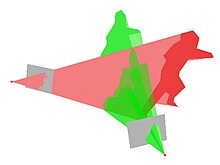
Projection of P on both cameras
Trouble statement & Basics [edit]
To reconstruct 3-D images from 2-D images taken by a camera at multiple angles. Medical imaging techniques like CT scanning and MRI are expensive, and although CT scans are accurate, they can induce high radiation doses which is a take a chance for patients with certain diseases. Methods based on MRI are not accurate. Since we are exposed to powerful magnetic fields during an MRI scan, this method is non suitable for patients with ferromagnetic metal implants. Both the methods can be done only when in lying position where the global structure of the os changes. So, nosotros discuss the following methods which can be performed while continuing and require depression radiations dose.
Though these techniques are 3-D imaging, the region of interest is restricted to a slice; data are caused to grade a time sequence.
Stereo Corresponding Point Based Technique [edit]
This method is simple and implemented by identifying the points manually in multi-view radiographs. The first step is to excerpt the corresponding points in two x-ray images. The second step is to reconstruct the image in three dimensions using algorithms like Discrete Linear Transform (DLT).[13] The reconstruction is only possible where at that place are Stereo Respective Points (SCPs). The quality of the results are dependent on the quantity of SCPs, the more SCPs, the amend the results [fourteen] but it is slow and inaccurate. The skill of the operator is a gene in the quality of the image. SCP based techniques are not suitable for bony structures without identifiable edges. More often than not, SCP based techniques are used every bit part of a process involving other methods.[fifteen]
Not-Stereo corresponding profile method (NCSS) [edit]
This method uses Ten-ray images for 3D Reconstruction and to develop 3D models with low dose radiations in weight bearing positions.
In NSCC algorithm, the preliminary step is adding of an initial solution. Firstly anatomical regions from the generic object are defined. Secondly, manual second contours identification on the radiographs is performed. From each radiograph 2d contours are generated using the 3D initial solution object. 3D contours of the initial object surface are projected onto their associated radiograph.[fifteen] The second association performed betwixt these 2 set points is based on point-to-point distances and contours derivations developing a correspondence betwixt the 2D contours and the 3D contours. Next step is optimization of the initial solution. Lastly deformation of the optimized solution is done by applying Kriging algorithm to the optimized solution.[16] Finally, by iterating the final step until the altitude between ii set points is superior to a given precision value the reconstructed object is obtained.
The advantage of this method is it can be used for bony structures with continuous shape and it also reduced human being intervention but they are time-consuming.
Surface rendering technique [edit]
Surface rendering visualizes a 3D object as a set of surfaces called iso-surfaces. Each surface has points with the aforementioned intensity (called an iso-value). This technique is normally applied to high contrast data, and helps to illustrate separated structures; for instance, the skull can be created from slices of the head, or the blood vessel organisation from slices of the body. Ii master methods are:
- Profile based reconstruction: Iso-contours are attached to each other to class iso-surfaces.[17]
- Voxel based reconstruction: Voxels of the aforementioned intensity value are used to form iso-surfaces. Popular algorithms are Marching Cubes, Marching Tetrahedrons and Dividing Cubes.[17]
Other methods apply statistical shape models, parametrics, or hybrids of the ii
Meet also [edit]
- 3D pose estimation – Process of determining spatial characteristics of objects
- 3D reconstruction – Process of capturing the shape and appearance of real objects
- 3D photography
- 2nd to 3D conversion – Process of transforming 2D film to 3D class
- 3D information acquisition and object reconstruction
- Epipolar geometry – Geometry of stereo vision
- Camera resectioning
- Computer stereo vision – Extraction of 3D data from digital images
- Structure from move – Method of 3D reconstruction from moving objects
- Comparison of photogrammetry software
- Visual hull
- Human image synthesis – Estimator generation of man images
References [edit]
- ^ "Soltani, A. A., Huang, H., Wu, J., Kulkarni, T. D., & Tenenbaum, J. B. Synthesizing 3D Shapes via Modeling Multi-View Depth Maps and Silhouettes With Deep Generative Networks. In Proceedings of the IEEE Conference on Computer Vision and Pattern Recognition (pp. 1511-1519)". half dozen March 2020.
- ^ a b C. Tomasi and T. Kanade, "Shape and move from image streams under orthography: A factorization approach", International Journal of Calculator Vision, 9(ii):137-154, 1992.
- ^ A. Laurentini (Feb 1994). "The visual hull concept for silhouette-based image understanding". IEEE Transactions on Pattern Analysis and Machine Intelligence. 16 (2): 150–162. doi:x.1109/34.273735.
- ^ R. Mohr and E. Arbogast. It tin be done without camera calibration. Pattern Recognition Letters, 12:39-43, 1991.
- ^ O. Faugeras. What can exist seen in three dimensions with an uncalibrated stereo rig? In Proceedings of the European Conference on Computer Vision, pages 563-578, Santa Margherita L., 1992.
- ^ E. Kruppa. Zur Ermittlung eines Objektes aus zwei Perspektiven mit innerer Orientierung. Sitz.-Ber.Akad.Wiss., Wien, math. naturw. Kl., Abt. IIa., 122:1939-1948, 1913.
- ^ S. J. Maybank and O. Faugeras. A theory of self-calibration of a moving camera. International Journal of Computer Vision, 8(2):123-151, 1992.
- ^ O. Faugeras and S. Maybank. Motion from signal matches: multiplicity of solutions. International Journal of Reckoner Vision, four(3):225-246, June 1990.
- ^ a b R. I. Hartley. Kruppa's equations derived from the key matrix. IEEE Transactions on Blueprint Analysis and Machine Intelligence, nineteen(2):133-135, Feb 1997.
- ^ Pollefeys, Marc. Self-calibration and metric 3D reconstruction from uncalibrated prototype sequences. Diss. PhD thesis, ESAT-PSI, KU Leuven, 1999.
- ^ R. Hartley and A. Zisserman. Multiple view geometry in estimator vision. Cambridge University Press, 2nd edition, 2003.
- ^ "Medical Visualization: What is it and what's information technology for?". GarageFarm. 2018-02-xviii. Retrieved 2018-02-xviii .
- ^ "Pearcy MJ. 1985. Stereo radiography of lumbar spine move. Acta Orthop Scand Suppl".
- ^ "Aubin CE, Dansereau J, Parent F, Labelle H, de Guise JA. 1997. Morphometric evaluations of personalised 3D reconstructions and geometric models of the human spine". Med Biol Eng Comput.
- ^ a b "S.Hosseinian, H.Arefi, 3D Reconstruction from multiview medical X-ray images- Review and evaluation of existing methods" (PDF).
- ^ Laporte, Due south; Skalli, W; de Guise, JA; Lavaste, F; Mitton, D (2003). "A biplanar reconstruction method based on 2d and 3D contours: application to distal femur". Comput Methods Biomech Biomed Engin. half dozen (1): 1–six. doi:10.1080/1025584031000065956. PMID 12623432. S2CID 3206752.
- ^ a b M.Scott Owen, HyperVis. ACM SIGGRAPH Pedagogy Committee, the National Science Foundation (DUE-9752398), and the Hypermedia and Visualization Laboratory, Georgia State University.
Further reading [edit]
- Yasutaka Furukawa and Carlos Hernández (2015) Multi-View Stereo: A Tutorial [one]
- Flynn, John, et al. "Deepstereo: Learning to predict new views from the globe's imagery." Proceedings of the IEEE Briefing on Computer Vision and Pattern Recognition. 2016.
External links [edit]
- 3D Reconstruction from Multiple Images - discusses methods to excerpt 3D models from obviously images.
- Visual 3D Modeling from Images and Videos - a tech-report describes the theory, do and tricks on 3D reconstruction from images and videos.
- Synthesizing 3D Shapes via Modeling Multi-View Depth Maps and Silhouettes with Deep Generative Networks - Generate and reconstruct 3D shapes via modeling multi-view depth maps or silhouettes.
overbeckthalowass.blogspot.com
Source: https://en.wikipedia.org/wiki/3D_reconstruction_from_multiple_images
0 Response to "generate 3d from a 2d drawing"
Postar um comentário